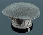
Loud-Speaker With Metal Grill::::
I thought I'd put the "flow on revolved surface" to the test - by making a mesh speaker grill.
If you have a speaker grill, you'd surely have a speaker, so lets make that:
The guts:
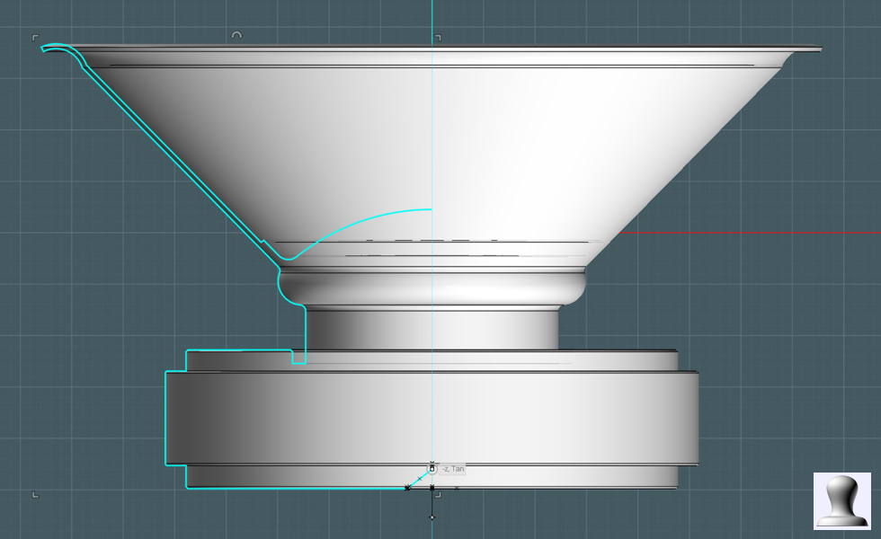
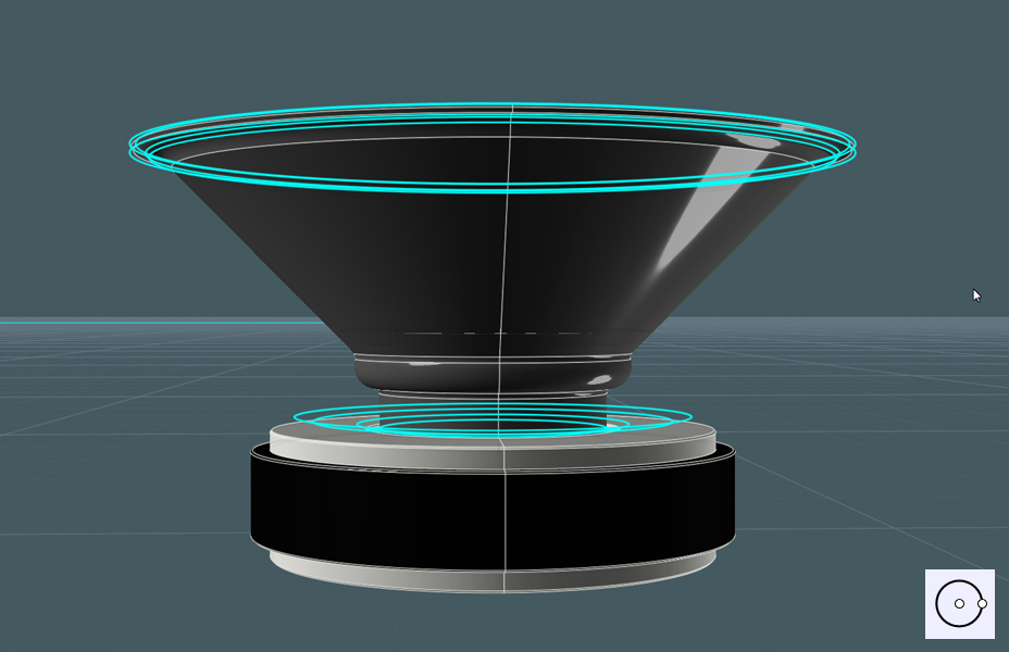
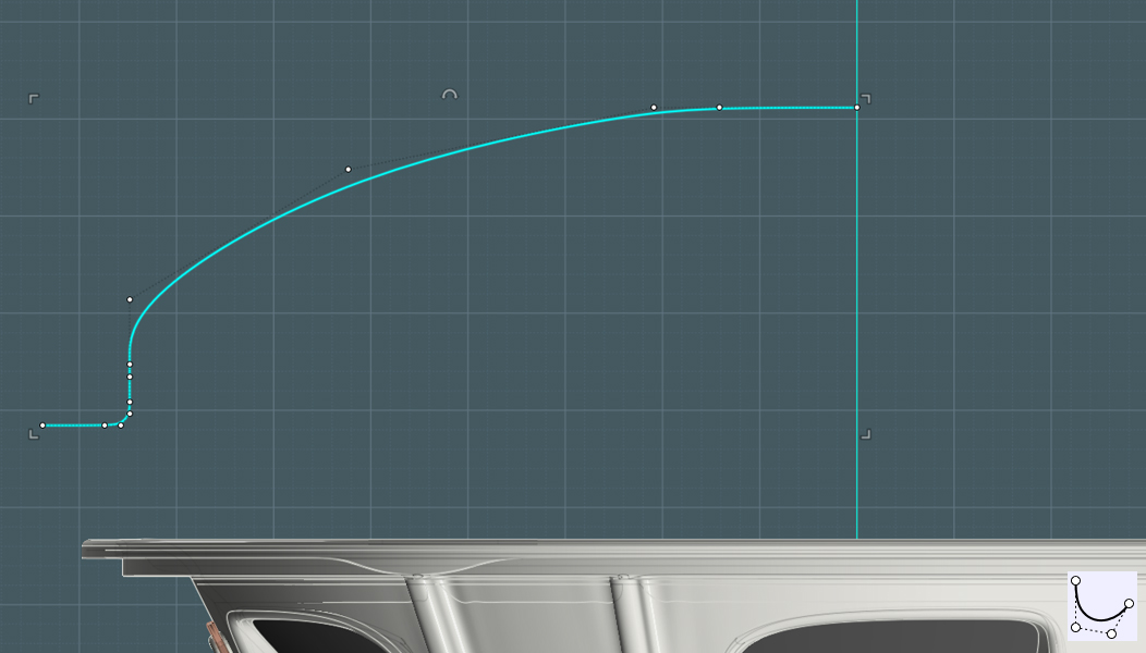
1) Draw a profile shape of half the side of the speaker assembly. Use lines, arcs, fillets and whatever else.
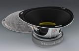
There are usually three main parts to the working guts of an audio
speaker - Magnet and core, solenoid are (often obscured), and the cone.
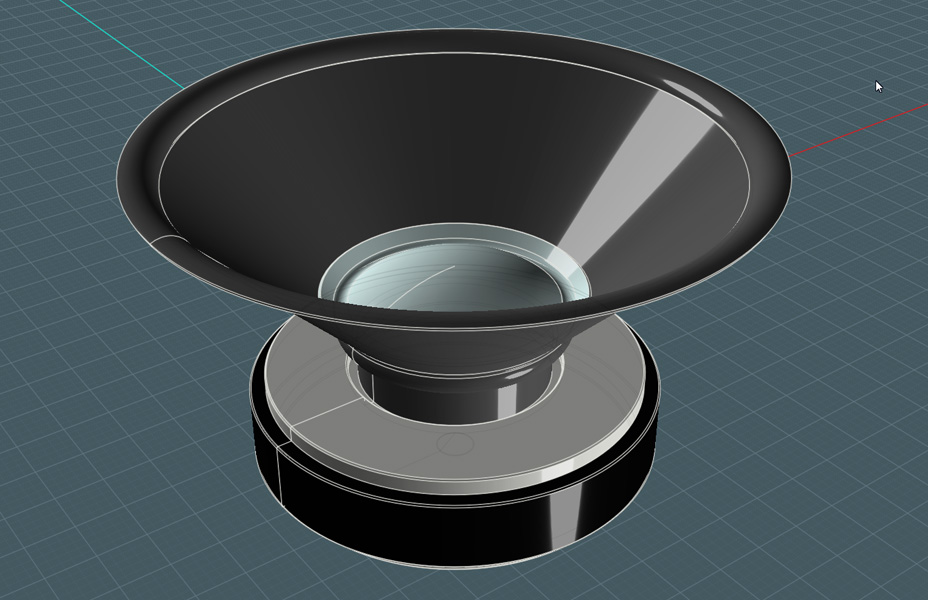
2) Revolve the profile to make the shape.
You are now 1/3 done!
Coloring:
- It helps to color the regions so that it is easier to prep for rendering later on.
Next, it the cone harness:
1) Draw a circle
2) Copy and position the circles to represent the main body of the harness - you'll see lower...
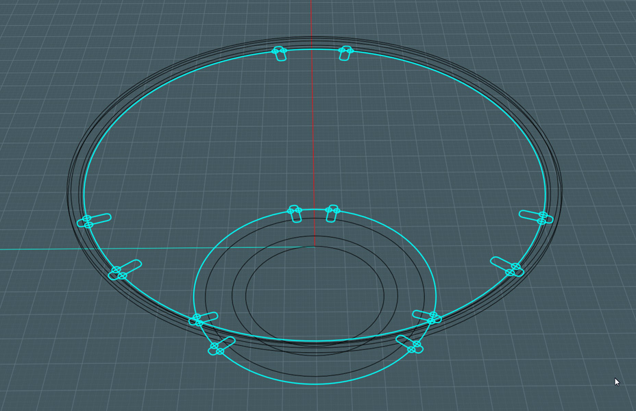
Support ribs:
- These will be a series of squared ridges that run up the harness body, they will have a consistent size along the length,
so they'll be lofted from two profiles carrying consistently sized ridges.
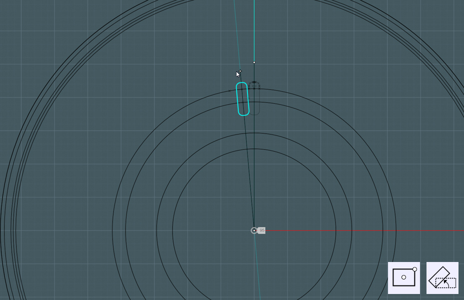
1) Draw a Rectangle with rounded corners.
2) Rotate to position - this is not necessary at this point, but it was what I did.
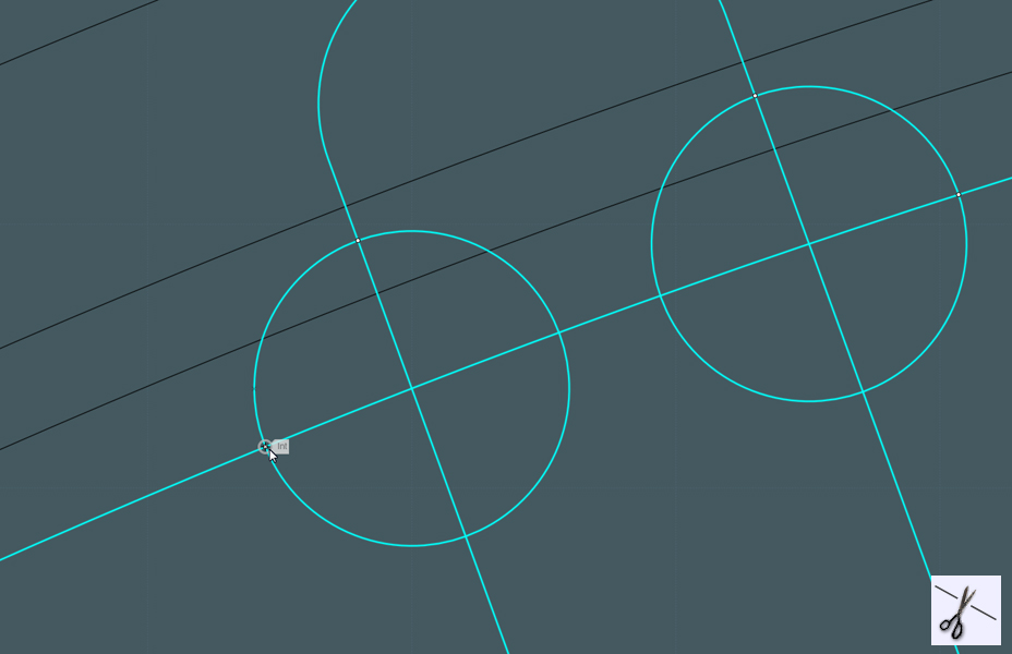
Make cuts:
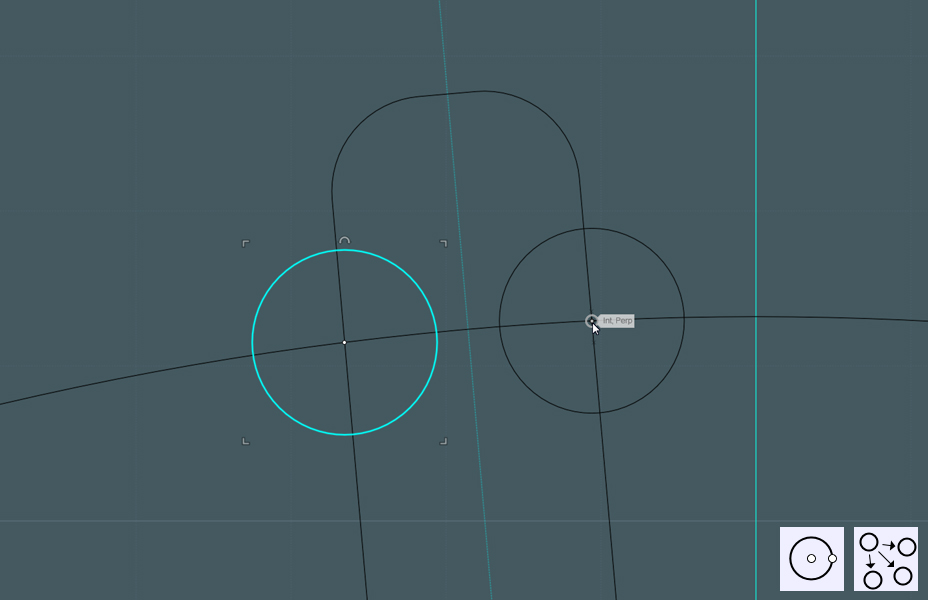
- We only need the top part of the rectangle and we also need a fillet.
1) Make a circle snapped to an intersecting point between one of your circles and the rectangle.
2) Copy the circle to the other intersection.
Rotate:
1) Either Rotational Array, or use Rotate snapping to the center and inputting a snap angle increment of appropriate degrees.
- I made two sets and made three copies around the perimeter.
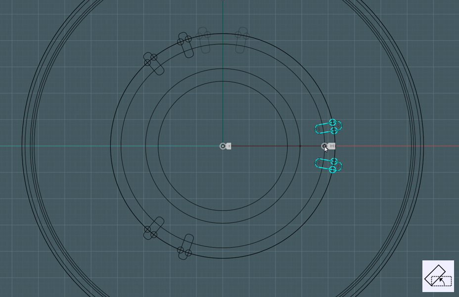
Two sets:
- do this for two rings, one near the bottom and one near the top.
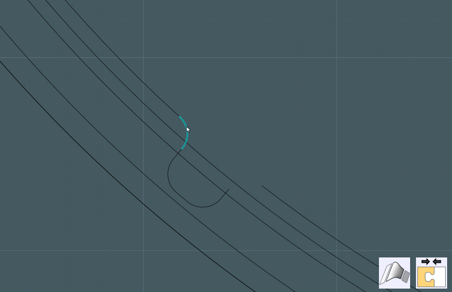
Trim:
1) Select the rectangles, small circles and large circles - Mutual Trim or Add Points.
2) Delete unneeded stuff.
Fillets:
- Blend the ends to make fillets.
You may also consider adding fillets to sharp corners.
Prep for blends:
- I want to blend the edges of this lofted harness body section,
The edges have to be one piece or there'll be difficulty later.
1) Rebuild profile rings so that they are one consistent spline with no cuts.
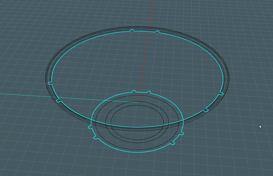
Loft to make harness body:
1) Loft new profiles.
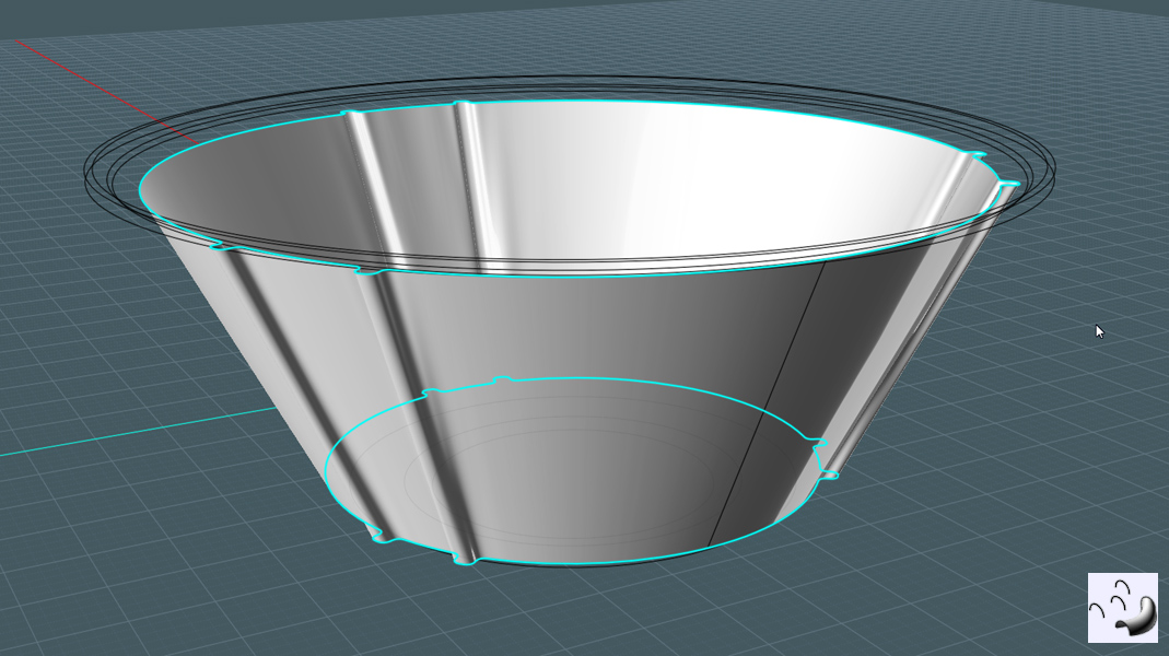
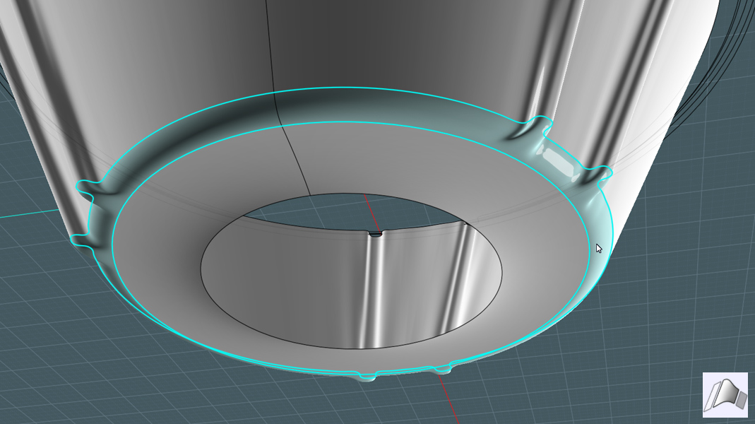
Loft to make bottom section:
1) Loft bottom rings together to leave a healthy gap between that and the bottom of the harness body.

Blend edges:
1) Select the edges of the two lofts - blend.
2) Join surfaces.
Create top ridges:
1) Loft top rings with the Straight setting.
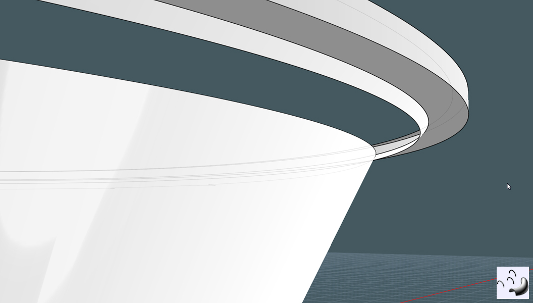
Blend edges:
1) select the edges of both the top of the harness and the bottom of the top ridge. - Blend to make a smooth transition.
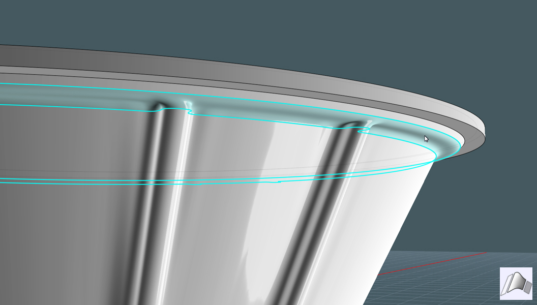
Smooth the ridge:
1) Fillet the corner edges of the top ridge.
2) Make sure the different sections are Joined.
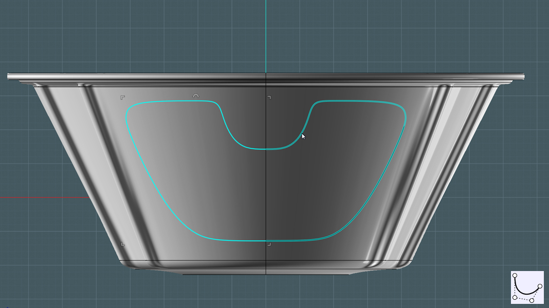
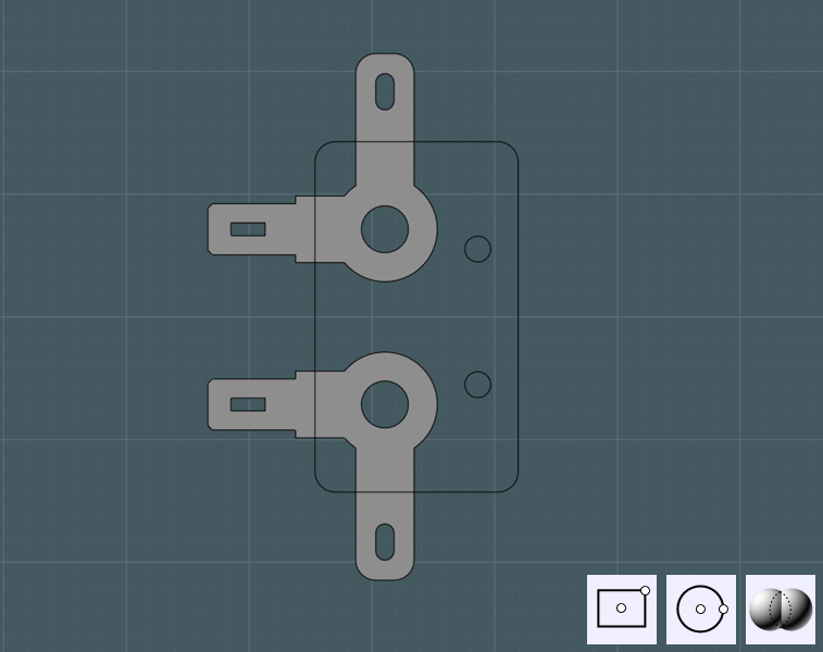
Make holes:
1) Draw a neat shape in a view port that represents a clear symmetrical side to the harness body.
2) Mirror and Join
Make copies:
1) Rotation Array to produce copies around harness body.
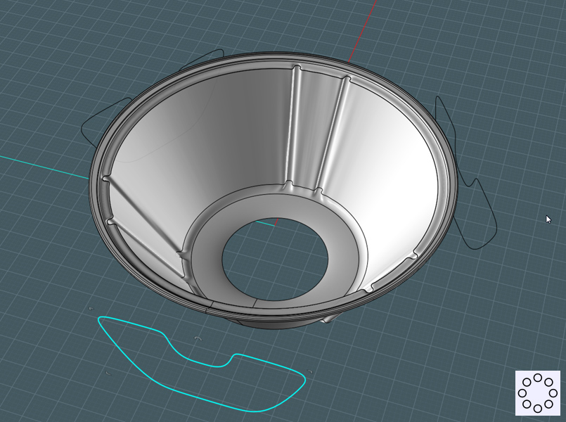
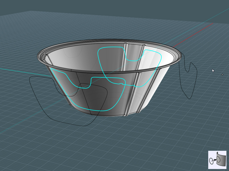
Projections:
1) Project each shape into the body sides through the center.
2) Delete back projection.
3) Trim projected shape into the harness shape.
4) Delete holes.
Punch-in:
1) Extrude the hole shape inward towards the center.
2) Join surfaces.
Round edges:
1) Fillet the edges.
Shell:
1) Shell or Offset surface to add thickness to the harness object.
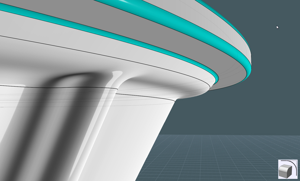
Nice edges:
- If your edges between the original harness body and it's offset surface are not solid,
give them a nice edge with an edge Blend.
1) Select edges, Blend
2) Join
- If you used a box method that worked to make a solid shape, then use Fillet.
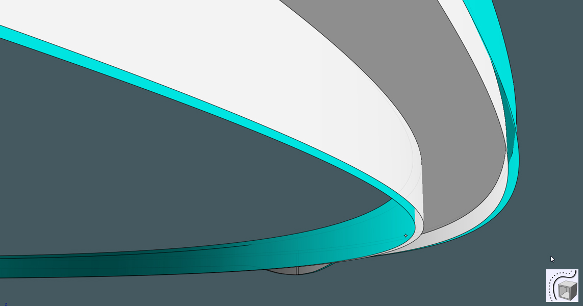
Harness brace flange:
- We need an interesting looking flange section at the top with three adjustable screw holes.
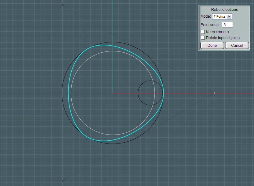
We need a "cam" shape, which is a three-sided triangular shape with extremely rounded corner.
A cam always has a consistent distance from one side to the other through the center.
I don't know if that is true for my shape here.
1) Make circle
2) Rebuild using # of Points = 3. You get a spline made from only three points!
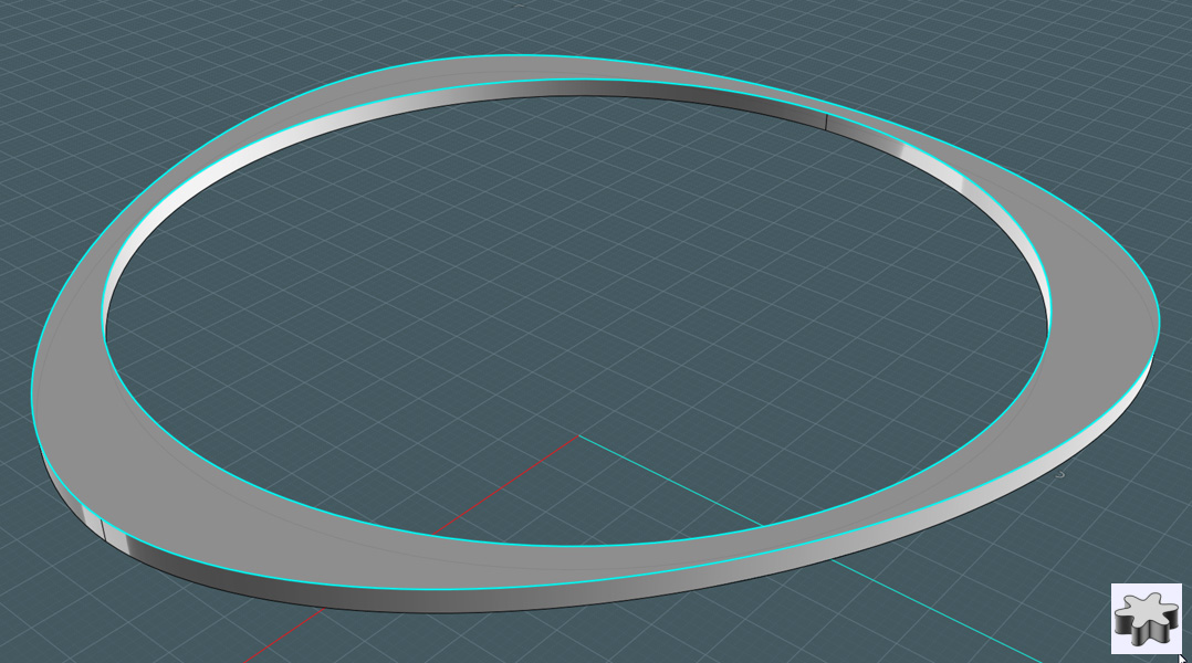
Thicken:
1) Extrude a combination of the outer cam shape and an inner circle representing the cone diameter.
2) Delete the bottom surface, so that it is and open shape.
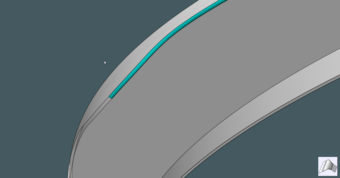
Interesting edges:
1) Draw a free-form curve to make the shape. Mirror and join.
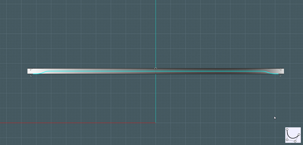
Cut:
1) Project the shape to the edges of the cam's extrusion.
2) Trim the front projection and delete the bottom portions.
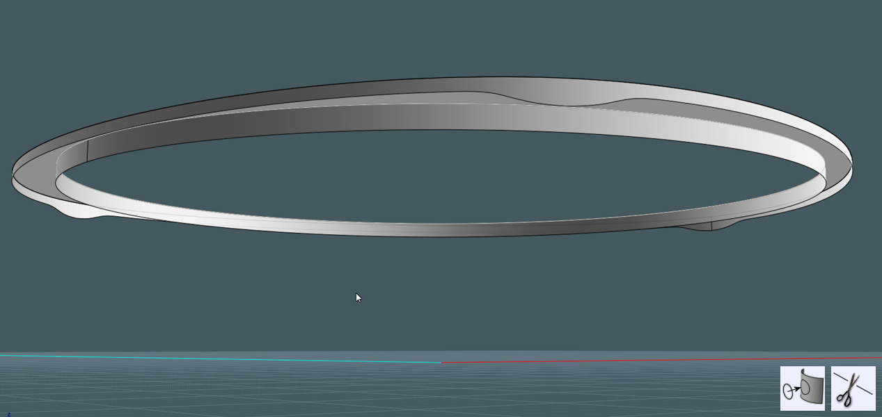
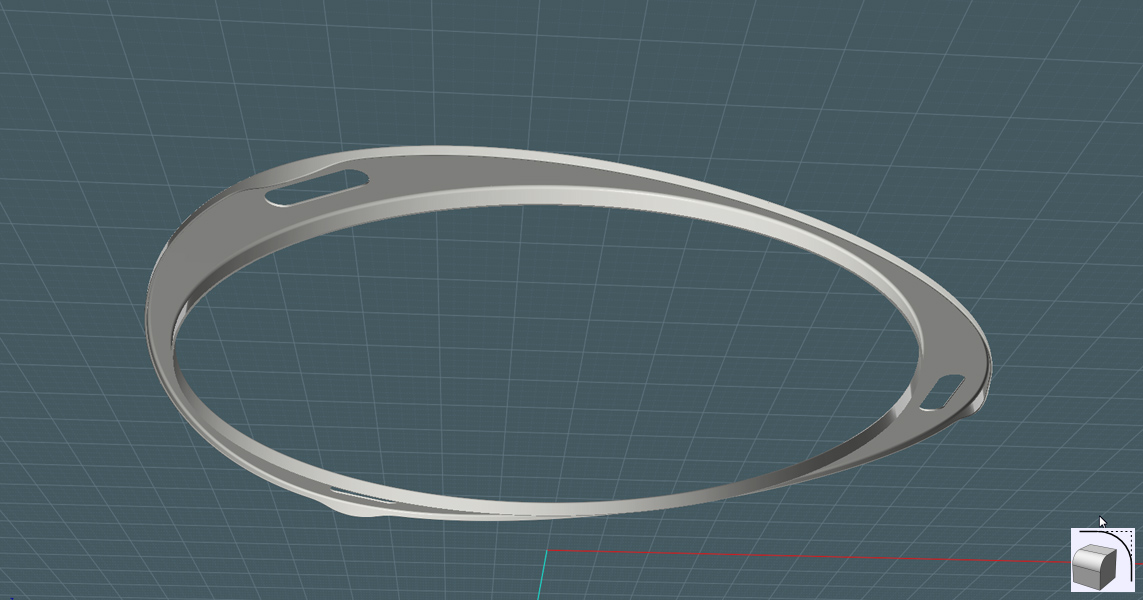
Add thickness:
- Run through the steps to create thickness on the harness body.
Make more nice edges:
1) Blend edges
2) Join
Smooth corners:
1) Select sharp corners of object and Fillet.
Terminator!
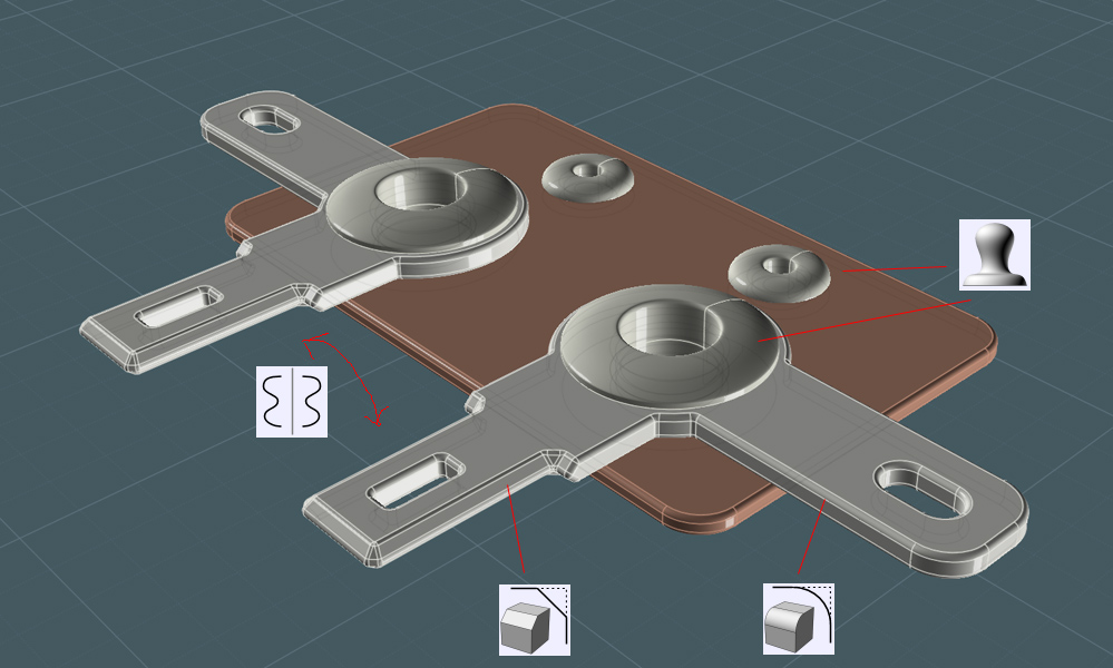
We need a terminal strip for the electrical connections.
1) Draw circles and rectangles
2) Boolean Union to create the shapes.
Construct:
1) Extrude the shapes.
2) Create rivets by making profile and Revolving.
3) Position the whole component on one of the tabs of the harness body.
- Because this is at a strange angle, use the Orient tool.
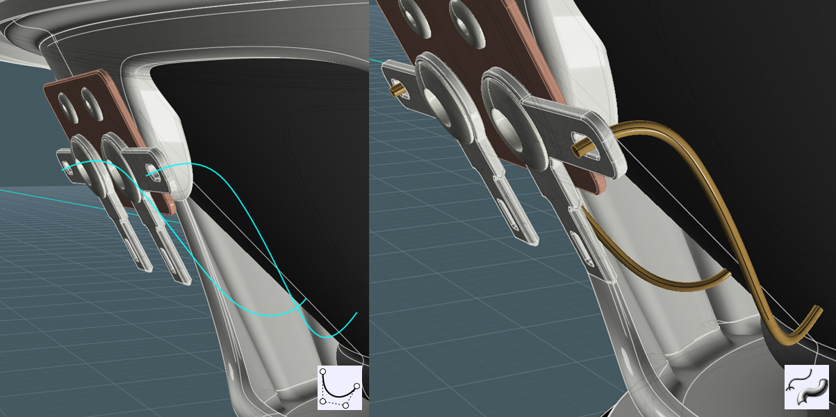
Wires:
1) Draw Free-form curves and edit their points to position.
2) Mirror one to make the other.
3) Draw circle and Sweep that shape along the curves.
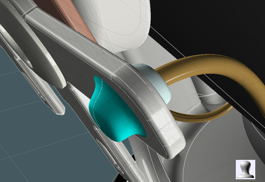
Solder:
Make a solder blob by Revolving a profile.
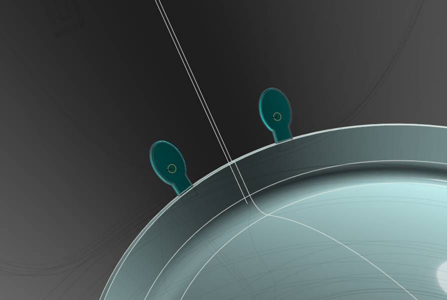
Details:
I made these reinforcement tabs to bring the wires to the inside surface of the cone, where wires go to the core solenoid.
I used shape projected to the cone surface, extrude and fillet.
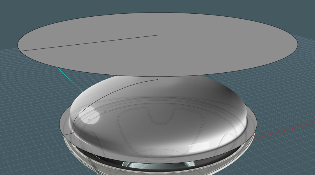
Come Down To the Mesh Grill:
1) Using Free-form curve in ONE single run, make the profile of the speaker cover grill basket.
If you do not have access to Moi3D V3 Beta - Here is an alternate method:
1) Revolve profile to make the cover's shape.
2) Array copies of lines (wavy) and Project them to the shape's surface.
3) Rotate this result to make a mesh
4) Sweep a circle along these projected lines
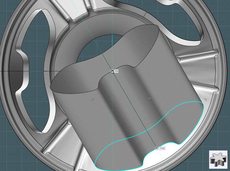
Matching:
1) Use Free-form curve to make a straight line curve.
- Match the points placement so that the physical point to point distances of the profile line are represented.
Think of the profile curve as being "unwrapped"
2) Revolve both profiles.
- NOTE: Move one of the straight curve points up or down a little. If you do not,
MoI will make a planar circle. We need a "Reference" circle with it's associated web knots.
3) Go to a side view and pull the editing handles of the top Reference surface until it is "Flat"
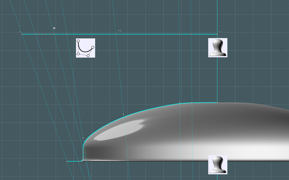
These are the Reference and Target surface for the V3 Beta Flow command...
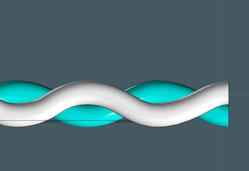
Wiggly:
To make a weaving mesh, each strand needs to wave - or be made from a sine wave to be exact.
Either use the sine wave script or make a representative section with the Free-form curve.
Copy these waves to make the extent of the mesh section and join.
Note: For Flow to operate expediently, it is important that each object section consist of one surface only!
Use Rebuild to reconstruct the sine wave curve section.
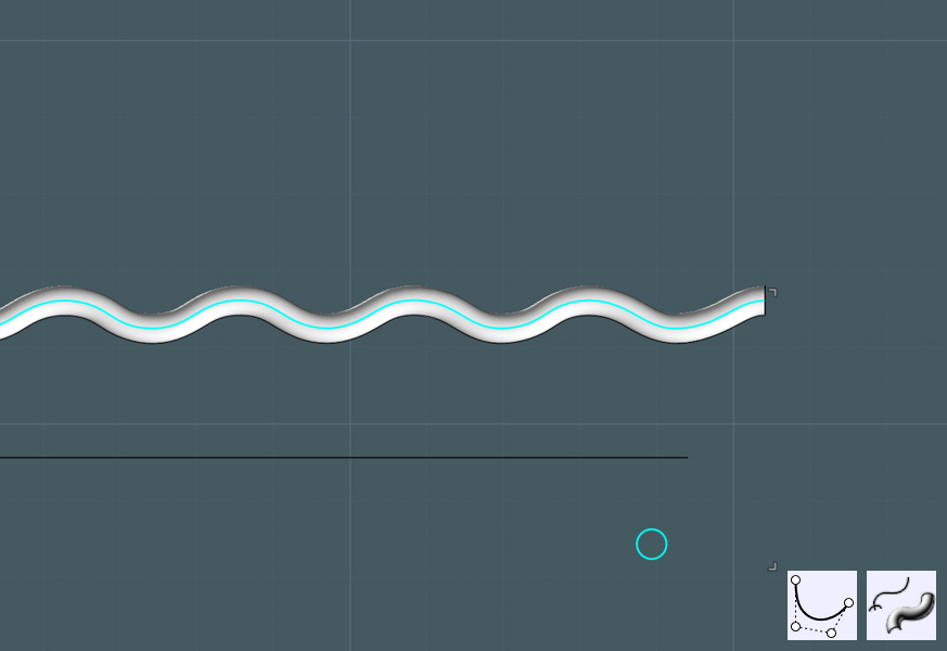
Since the sections weave under and over, make the next one over a flipped copy.
Array the sections to cover the span.
Make a rotated copy and flip to create the opposing weaves.
If your math and measurements are correct, you should have a seamless weave with no collisions.
...This was not my result. ;-)
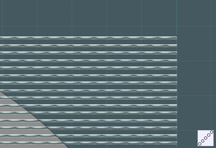
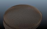
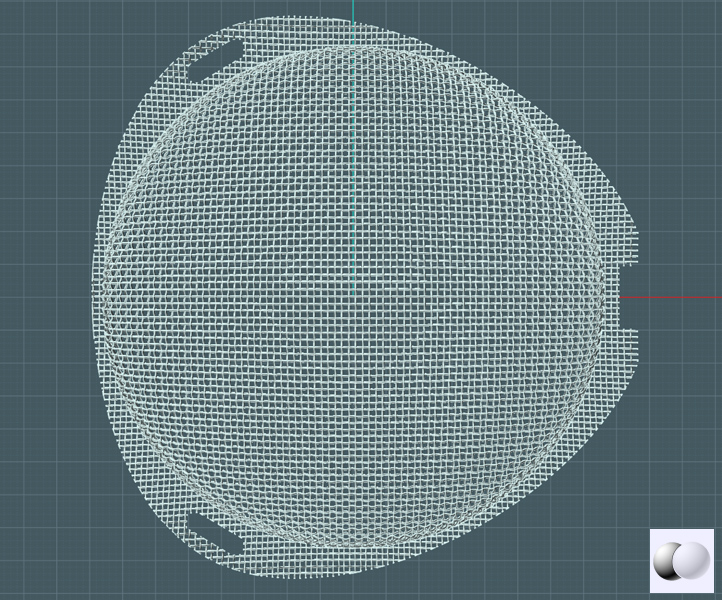
Here is the completed mesh in it's flat form. It is aligned with the Reference circle.
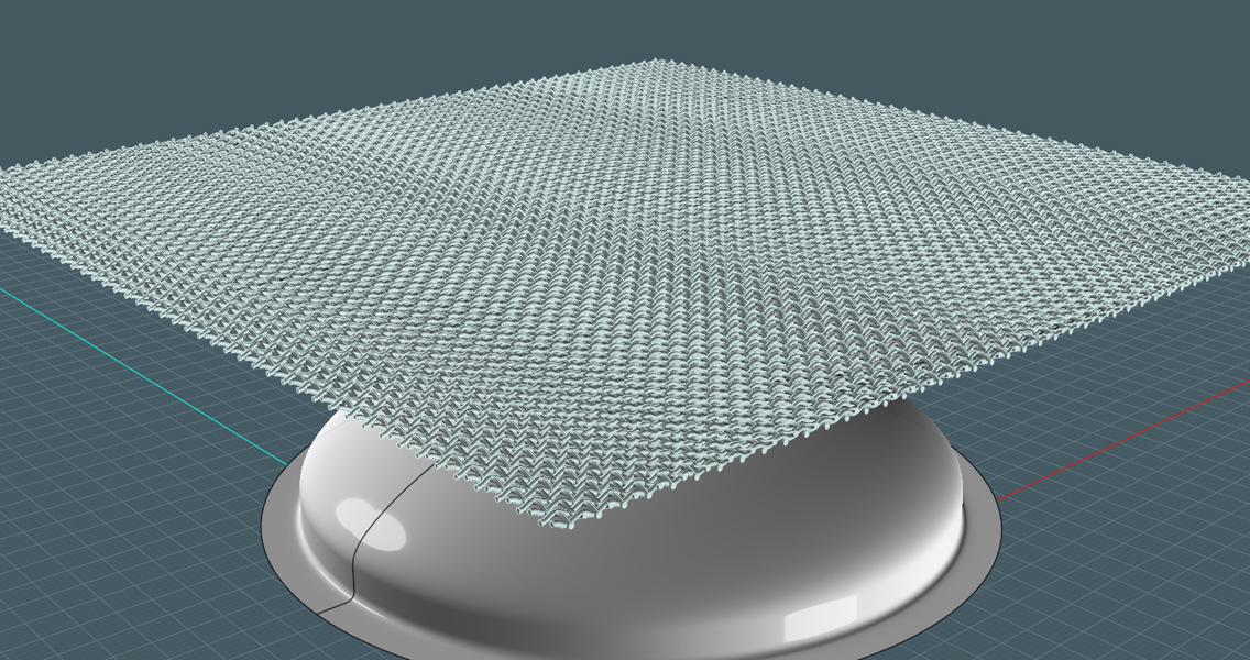
FLOW!!!
- Try the Flow command with only one section at first to gauge for time - try more at once if possible.
1) Flow will prompt you to select the object to flow.
2) You'll be prompted to select the Reference surface.
3) You'll be prompted to select the Target surface.
........wait........
It helps to have "delete original objects" to help organize the process.
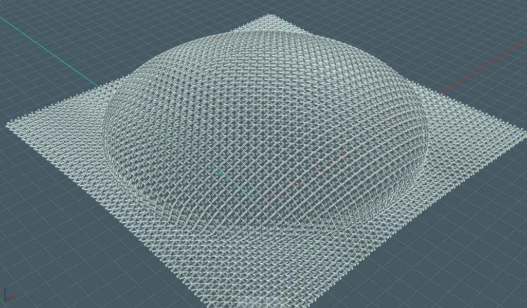
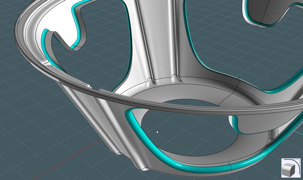
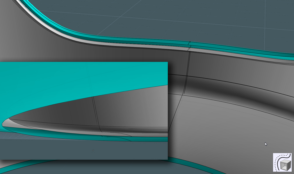
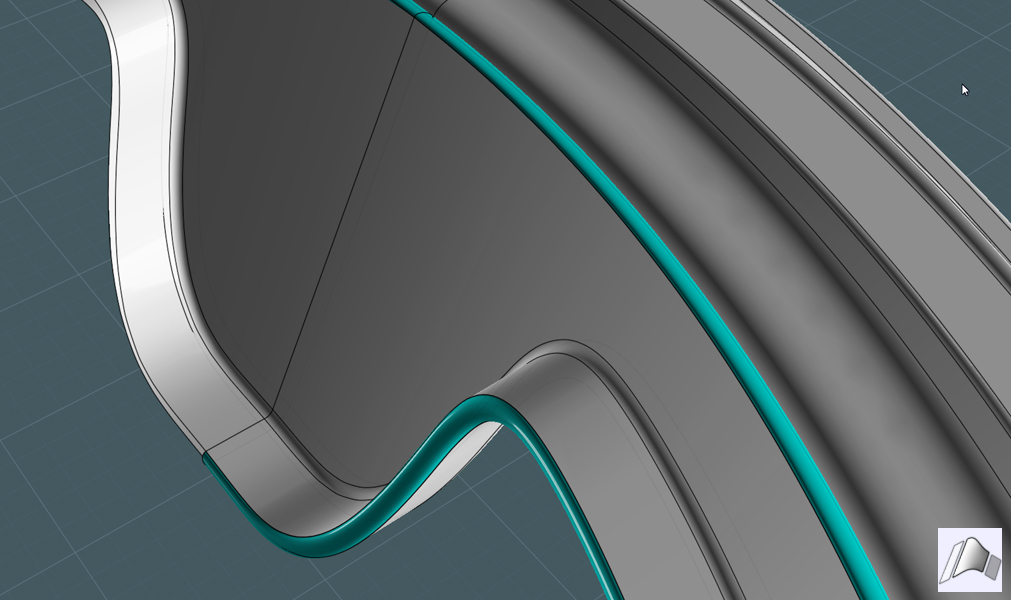
Trim:
Use the "cam" shape to trim the edges of the new formed mesh. Trim additional holes.
- I can say outright, that these objects did not want to all trim without error, do the best you can.
I also made a gasket to sandwich between the wire mesh and the flange.
That should be flatter copy of the cam/circle extrusion with the holes, all filleted.
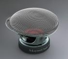
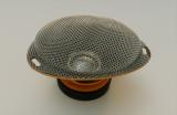
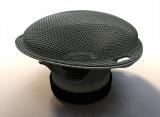
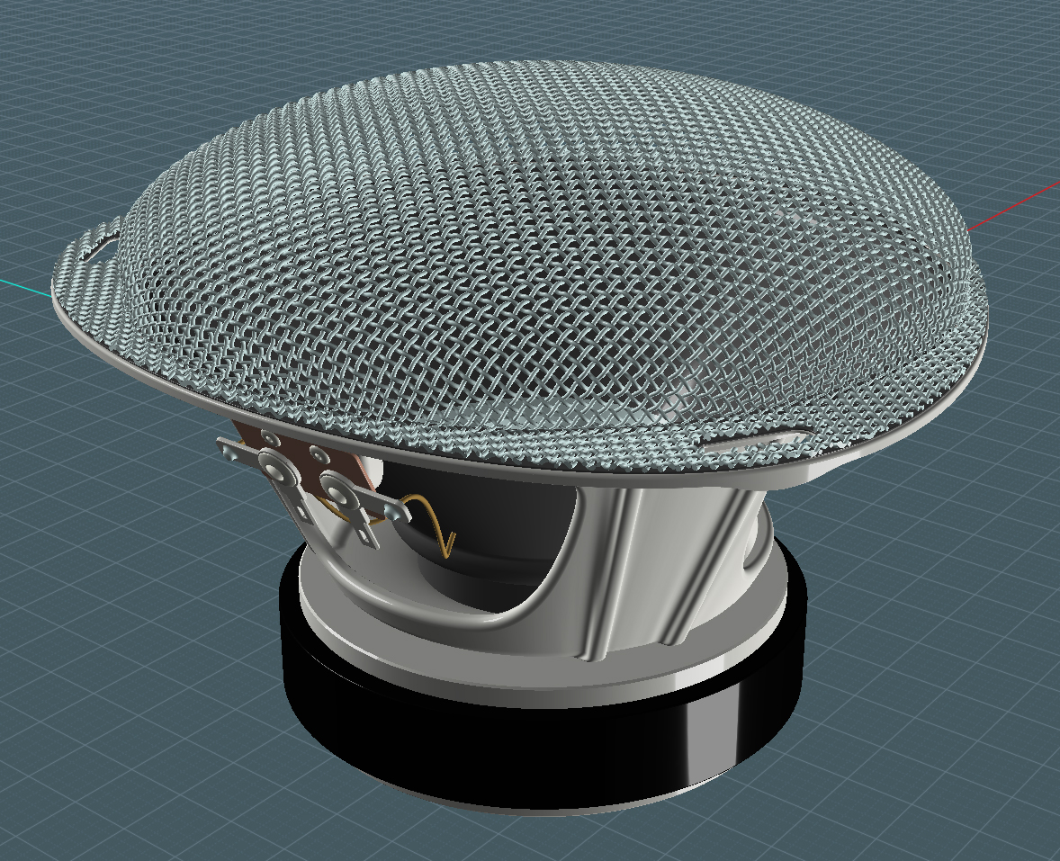
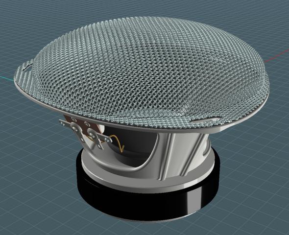
And Finally - it all comes together!
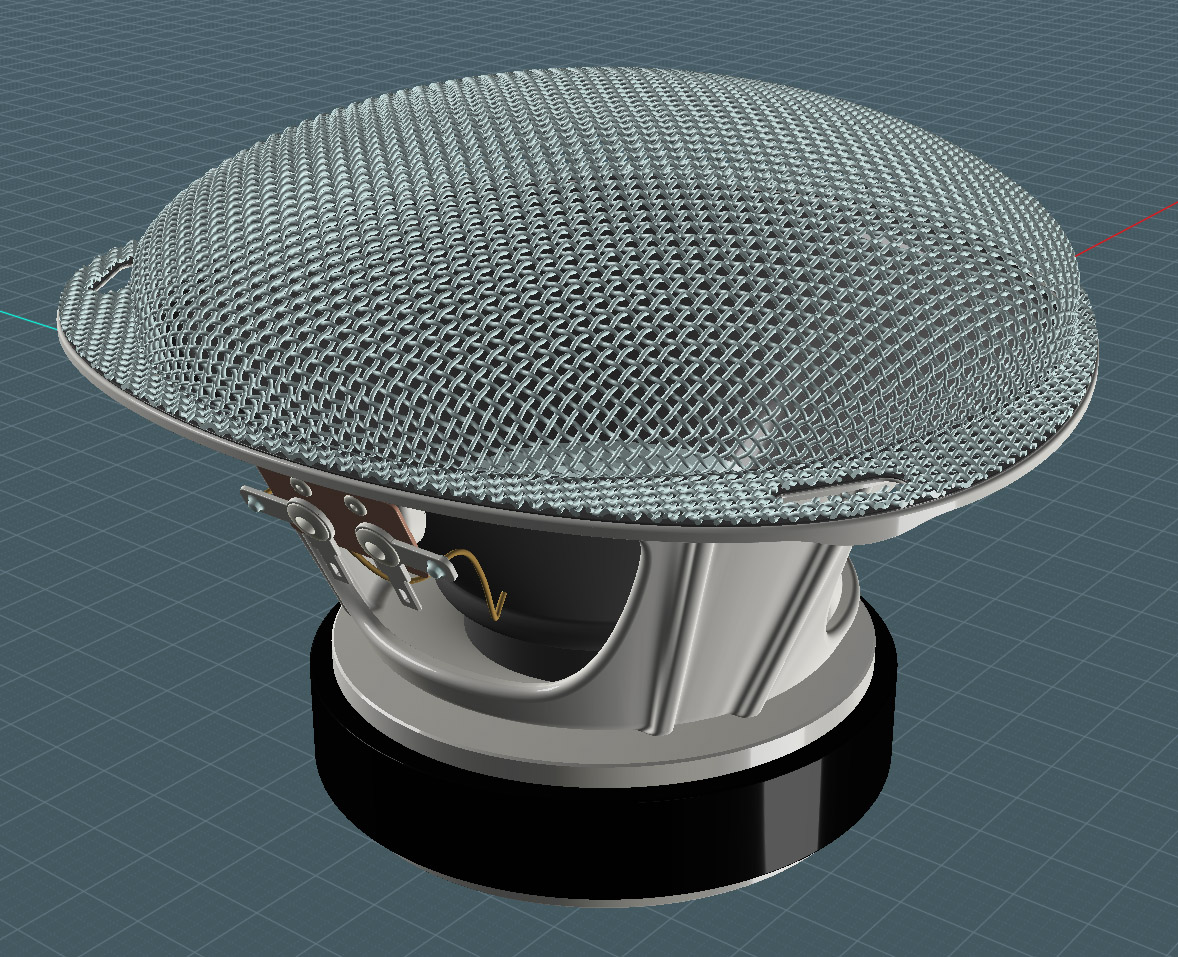
I will be trying some renders out soon,
until then if you like - feel free to download this model to check it out:
http://www.mediafire.com/?3tlre2zc6y1qh
Use it for your own projects where you require speakers for a boom box or audio system, add you own grill cover.
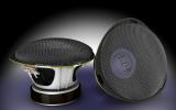
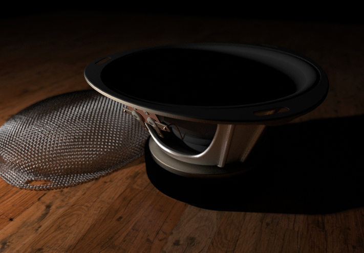
Following: is a rendered result of the model.
I
used Kerkythea Boost with Metropolis Light Transform (BPT) for the
mode, only a few passes, but this image was reduced by 2 to clear up
the noise.
Used one omni-light at a low angle. And a little F-Stop number tweaking on the camera.
Kerkythea is a free rendering application: Please visit: http://www.kerkythea.net/joomla/

Not bad for my little bit of knowledge with Moi3D-Kerkythea rendering.
After
I posted the tutorial for this model, there was a collaborative effort
to provide comparative renders - here is the Moi3D Gallery entry:
http://moi3d.com/gallery/viewitem.php?id=420
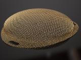
Moi Enthusiasts "Mesh" Together by "Majik" Mike Maynard View full size
The mesh object on top of the featured audio speaker is an exhibition of the power of Moi3D V3 Beta's new Flow tool.
Many whom graced the forum entry tried their hands at the export and rendering of this slightly complex model.
Presented is a simple visual comparison of different rendering platforms.
In order:
1) My screen-shot example
2) M-Dynamics (Gold Mesh)
3) Ed Ferguson (KeyShot, Grill separate)
4) Ed Ferguson (KeyShot, Grill combined)
5) OSTexo (Thearender 1.1)
6) BurrMan (3D Coat)
7) Grendel (Carrara)
8) Phil (Octane)
9) DanPerk (Modo Render)
10) Majik Mike (Kerkythea Boost)
Thank you guys! Hope I got everyone.
See the tutorial: http://moi3d.com/forum/index.php?webtag=MOI&msg=4561.1
Visit K4ICY for tutorials: http://k4icy.50webs.com/tutorials.html